
SYSTEM-LEVEL PARAMETERS AND OBJECTS
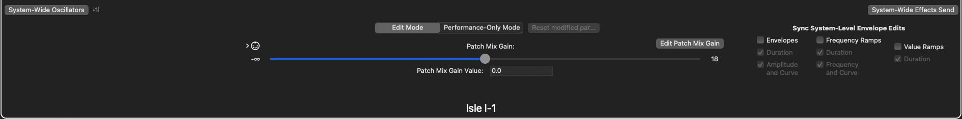
At the bottom of the main window, you’ll see system-wide parameters which affect the entire operation of the Isle I-1. All system-level objects and parameters, including the entire MIDI configuration and tuning system selection, are saved as part of the Patch Bank file – you can have totally different system setups for each Patch Bank.
In the upper-left corner of the bottom section, the System-Wide Oscillators button allows you to define Oscillators and entire modulation trees, which can be shared by any operator, in any Patch, in the Patch Bank. Oscillators which might have common settings across patches can be set up as system-level oscillators instead, and borrowed by each patch which uses it – in this way, one single copy of the oscillator is executed, and used by every running sound which references it, rather than separate copies of an oscillator for each patch, for each running sound of that patch. Another use for system-level oscillators is to set up low-frequency oscillators (LFOs), which may drive sirens, flanger sweeps, filter cutoff frequency modulations, or anything else, with these modulation points synced across all sounds.
In the upper-right corner, the System-Wide Effects Send button allows you to add effects to the system-level Effects Send. These effects are applied to all active sounds, on top of any effects active in the individual patches. Computationally-expensive effects, such as reverbs, are best placed here, as there is only one copy of the effect running, rather than one for each running sound. Adding and removing effects follows the same process as effects loops in other parts of the synth.
In the center of the bottom section is the system-wide Gain parameter – this affects the overall output of the system in decibels, ranging from negative infinity (total silence) to +18 dB. This parameter is fully modulatable, and can be assigned MIDI commands as well.
PERFORMANCE-ONLY MODE
All of the parameters on the Isle I-1 can be manipulated in real-time, via the UI controls themselves, or via external devices over MIDI. In Edit Mode, manipulating the UI not only modifies sounds in real-time, it alters the Patch configuration for all future sounds, too. Indeed, if your goal was strictly performance, and Edit Mode were the only mode, you would lose your original patches by dragging sliders around, destructively editing your patches while you played. Hence, Performance-Only Mode – in this mode, sounds can be infinitely manipulated via UI controls, without losing the original Patch settings. To turn on Performance-Only Mode, select it from the toggle buttons in the center of the system-level view, just above the Gain parameter. When you’re ready to put the original parameters back, click the Reset Parameters button. Certain UI controls, which only exist to modify the Patch and cannot reasonably changed or rolled back while performing (such as adding an Oscillator), are disabled in Performance-Only Mode.
SYSTEM SETTINGS
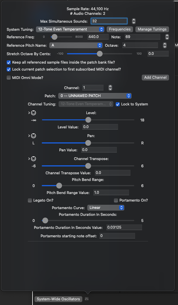
Clicking on the Parameters icon next to the System-Wide Oscillators button displays the System Settings view, as well as settings for each Control Channel. For Apple Audio Units, the Sample Rate and # of Audio Channels is controlled by the operating system. You can change it, per Audio Device, in the Audio MIDI Setup app in your Applications | Utilities folder, or via GarageBand, Loic Pro, or other DAW application. They are presented on this panel for reference and convenience.
System Tuning Parameters
Below these values are parameters related to the overall active System Tuning. This is basically the tuning table mapping note numbers to frequencies. Chapter 8 describes the tuning system, available tunings, and how to build a custom tuning in full — it is pretty full-featured and worth checking out if you’re interested in tunings other than the usual 12-Tone Even Temperament. At the System level, you can select from any canned tuning algorithm or a custom tuning that you’ve modified or imported from a tuning file. The Frequencies button will show you the frequency values for every defined note — you are not limited to the notes 0-127 displayed on this panel — while MIDI 1.0 can only send note numbers in this range, the Isle I-1 engine has no such restrictions and views the note system extending infinitely (well, max size of a 64-bit integer) in either direction. For Custom Tunings, this panel is where you will find the customization features — again, read Chapter 8 for full details.
The Manage Tunings button shows a list of all custom tunings present in the system, including tunings imported from external files (Scala .scl files, which may include Ableton’s extensions to the format). Reorder tunings in the tuning dropdowns, export a tuning to a Scala (.scl) file, import a new tuning, or remove an unneeded custom tuning from this panel.
The next 2 lines contain common parameters for every tuning system. Reference Frequency and Reference Note Number define the origin of the tuning system — tunings are (nearly) always defined relative to this frequency, and that frequency is mapped to the note at Reference Note Number. Below these parameters, the corresponding note name and octave number define the tuning system’s note name for the reference frequency — for example, 12-Tone Equal Temperament defines its set of note names as the conventional Western note names. By default, its reference frequency is 440 Hz, at note number 69. The name of this note is A, at octave 4, commonly referred to as note A4. Middle C, below this note, sits at note 60; based on the selected tuning system, the calculated frequency value for C4 at note 60 is approximately 261.625 Hz. If you change the reference frequency to 264 Hz, the reference note number to 60, and the reference note name to C, you will see that note number 69 now has a calculated value of 443.993 Hz, and it is still named A4.
The Stretch Octave parameter is below Reference Pitch Name and Octave. This parameter stretches an octave (or other Interval of Equivalence) by as much as +/-100 cents. Slightly stretching an octave is a fairly common scenario, regardless of the selected tuning system. This slider will adjust any active sounds subscribing to the system tuning in real time. All pitches defined within the octave will stretch with the octave, proportionately. See Chapter 8, Tunings, for a more complete description.
Keep all referenced sample files inside the patch bank file?
Below the Tuning settings, and just above the MIDI settings, is the checkbox to keep all referenced samples within the Patch Bank file. You may wish to do this to make it easy to share your Patch Bank files with other Isle I-1 users, or you may simply wish to do this for convenience. This feature is pretty stratightforward — if you check the box, a copy of the sample file will be kept inside the Patch Bank file, and all references to the file within the Patch Bank will reference the internal copy. The original file is not moved or deleted; it will still exist, untouched, on your file system. Additionally, the Patch Bank copy is not altered from the original in any way — it retains its original format and resolution. While the Patch Bank file format is itself a zip file, and within the zip file any audio files might gain some slight (lossless) compression, the zip compression algorithms do not specifically perform any audio compression.
MIDI 1.0 SUPPORT
Being a software synthesizer, running on a laptop or PC, with limited native interfaces for playing or manipulating sounds, the Isle I-1 offers a full implementation of MIDI 1.0. Via MIDI, any device which can transmit messages and act as a MIDI controller can be used to control the Isle I-1.
MIDI 1.0 defines 16 channels on which messages can be sent between devices. The I-1 can listen on any combination of 16 channels. A new Patch Bank is set up to listen on MIDI Channel 1. Additionally, the I-1 can listen in Omni Mode, processing messages received on any channel. This can be a quick way to get a controller to work with the I-1, and can also be useful in troubleshooting MIDI connection problems. To change the MIDI configuration, click the MIDI Settings icon, to the right of the System-Wide Oscillators button on the system-level view. Omni Mode can be turned on or off via the MIDI Omni Mode checkbox.
- When Omni Mode is OFF:
- The I-1 can listen on one or more channels. To add an additional channel, click the Add Channel button. A new subscription will be created for the lowest available channel number.
- To remove a channel subscription, click the red X button for the channel in the channel list. There must be at least one active channel subscription – if there is only one, you cannot remove it.
- Lock current patch selection to first subscribed MIDI channel
- Each channel can be assigned its own Patch from the current Patch Bank. It can be intuitive to expect sounds to be made from the currently selected/displayed Patch in the Patch Editor.
- When this option is checked, the lowest-numbered subscribed MIDI channel will always trigger sounds from the currently selected/displayed Patch.
- Change the channel number of a channel subscription by editing in the Channel Number edit box, or by using the stepper controls. If a channel number is already subscribed, the stepper will skip it, and the edit box will not accept the entry. The channel subscription list will always display in channel order, so as you step the channel number up or down, you may see the channel’s settings move in the list.
- As previously mentioned, a channel can be assigned its own “current patch.” Note On messages sent on this channel will play sounds based on the channel’s “current patch.”
- Each channel has a Level and Pan parameter – channels can be mixed individually. MIDI controller number 7 (channel volume) is automatically assigned to Level, and controller number 10 (channel pan) is automatically assigned to Pan (they can additionally be assigned to any other parameter in a patch). The MIDI specification also defines controller 8 as “channel balance” – since I am not implementing an ‘80’s boom box, controller number 8 is also automatically assigned to Pan.
- Channel Transpose can transpose the pitch of any sounds on a channel up or down by a relative number of octaves. The Pitch Bend controller is automatically assigned to this parameter, so that Pitch Bend “just works” out of the box. You can limit the range of the Pitch Bend wheel per channel, also in units of relative octaves. The default range is ±1 octave.
- Legato and Portamento — The MIDI parameters panel can be used to turn Legato and Portamento on/off for a channel, though this is probably better done via MIDI commands from, say, a footswitch.
- When Legato is On, new Note On commands which happen before a Note Off is received do not start new sounds, but change the pitch of an existing sound immediately, and without restarting any envelopes. MIDI controller 68 (legato footswitch) is automatically assigned to this parameter.
- When Portamento is On, behavior is very similar to Legato On, in that new Note On commands simply change the pitch of an active sound instead of starting new sounds, and again, no envelopes are restarted. The change in pitch is ramped over time and occurs along a curve, instead of immediately jumping to a new pitch. MIDI controller 65 (portamento footswitch) is automatically assigned to this parameter. Portamento settings can be assigned to each individual channel – duration of pitch change is specified in seconds (MIDI controller 5 is automatically assigned to this parameter), and available curve types are Linear, Logarithmic, Exponential, and Noop (No Operation). Logarithmic and Exponential curves also include a Power parameter. Squared and Cubed curve types are convenience implementations of the Exponential curve, with the Power parameter hard-coded to 2 and 3, respectively.
- The MIDI 1.0 specification designates controller number 84 as “portamento control,” to specify a starting note for a new portamento sound. This controller is automatically implemented in the I-1.
- A MIDI Channel can use its own tuning system. As this is admittedly a bit of an edge case, for conveience, it is typical to lock a channel’s tuning to the overall System Tuning via that channel’s checkbox. However, if you deselect the Lock checkbox, you will be able to select a different tuning for this and only this channel. All customization options are available to a single channel, as well.
- When Omni Mode is ON:
- The Isle I-1 processes MIDI events on all 16 channels. There are two Omni Modes in the Isle I-1 – Monotimbral and Multitimbral – you can select from the toggle button which replaces the Add Channel button.
- In Monotimbral mode, there is only one set of MIDI parameters, which is applied to every channel. As the name implies, all sounds are generated from the same Patch, which may or may not be locked to the currently selected/displayed Patch in the Patch Edit view. The remaining parameters work just as they do in non-Omni Mode.
- Multitimbral mode works as though Omni mode were not selected and the I-1 was configured to subscribe to all 16 channels. Each channel gets its own set of MIDI parameters, and can be independently assigned its own “current Patch” and tuning. Channel 1 can be locked to the currently selected/displayed Patch. In Omni-Multitimbral mode, you cannot unsubscribe from a channel or subscribe to a new channel (as there are no more available channels).
Any runtime parameter available in any Patch or at the System Level can subscribe to any MIDI event (except for System Exclusive events). You will notice a 5-pin DIN icon to the left of each parameter name, with a right-pointing arrow. If this icon is white, the parameter does not subscribe to any MIDI events; however, if it is glowing green, it does subscribe to MIDI events.

IMPORTING YAMAHA DX7 SYSEX DUMPS
The Isle I-1 imports bulk sysex dumps from the Yamaha DX7. Such dumps contain 32 patches, and comprise an entire ROM cartridge. The files must have a file extension of .syx, and the data must start with the System-Exclusive indicator (0xF0) in the first byte; include the Yamaha manufacturer code, decimal 69 or hex 0x43, as the 2nd byte of data; and indicate the bulk dump format, 0x09, as the 3rd byte of data. Individual patches are converted into Isle I-1 patches. DX7 parameters and objects are converted to Isle I-1 parameters and objects, as follows:
- Patch algorithms are built directly as Isle I-1 algorithms — the patch view should be pretty recognizable as the corresponding DX7 algorithm diagram. Individual DX7 operators are Isle I-1 Oscillators, each generating a sine wave.
- Operator Output Level corresponds to Frequency Modulation Settings’ Level in the I-1 Carrier Oscillator. For algorithms where a modulator affects multiple carriers, such as algorithm 22, this value will be reflected in each carrier’s FM Settings. If a DX7 operator is in Frequency Ratio mode, I-1 frequency is in units of Frequency Ratio; if in Fixed mode, I-1 frequency is in units of Hz. Coarse and Fine are combined into this representation. DX7 Tune is translated to I-1 Oscillator Detune; each detune notch on the DX7 corresponds to roughly 1.12 cents, which is reflected in the I-1.
- Operator Output Level for operators which go directly to audio output is reflected in the I-1 Mixer’s Mix Levels settings for each oscillator. Operator Output Level is also reflected in each carrier Oscillator’s Modulation Depth setting in its FM Settings. Modulation Depth is in units of Frequency Ratio, and maximum DX7 Output Level results in Modulation Depth of 4π (12.57).
- Each DX7 Operator’s envelope is converted directly to the corresponding I-1 Oscillator’s envelope. For each stage, DX7 Level is converted to I-1 Level in dB; The DX7 Rate parameter does not directly translate to I-1 Duration — instead, the duration of a DX7 envelope stage is affected by both the Rate and Level parameters. The I-1 Duration parameter (in seconds) is set accordingly. The DX7 can produce envelope segment durations as long as 325 seconds. You may see a 0-second stage inserted anywhere where the DX7 envelope starts from Level 0 — the DX7 actually jump-starts such envelope attack stages. The 0-second I-1 stage accomplishes this. The DX7 immediately jumps to the 4th stage on key up; thus, the I-1 stage corresponding to the 3rd DX7 stage is set as the Sustain stage. For operator amplitude envelopes, ascending envelope stages use a Logarithmic curve; descending stages use the Linear curve.
- DX7 Key Tracking, via each operator’s Breakpoint, L Depth, R Depth, L Curve, and R Curve parameters, are mapped pretty directly to Key Tracking in each affected I-1 Carrier’s (or the Mixer’s) Level parameter. The effective breakpoint value of the DX7 is actually 2 notes BELOW the value specified on the DX7; this is reflected in the I-1 conversion. DX7 Rate Scaling is applied to each envelope stage’s Duration value as Key Tracking, starting from a minimum MIDI note of 21 and applied with a linear curve through a maximum MIDI note of 114. Isle I-1 Key Tracking is only created and applied if the DX7 had L Depth or R Depth greater than 0, or in the case of Rate Scaling, if the DX7 Rate Scaling parameter was greater than 0.
- DX7 Operator Velocity Sensitivity, when greater than 0, is converted to Velocity Tracking on the carrier’s (or Mixer’s) Level parameter. Just as on the DX7, it can cause the operator level to exceed 0dB, though there is also a cap on this effect, reflecting the DX7’s limits.
- DX7 Feedback maps to the feedback oscillator’s Modulation Depth (in units of Frequency Ratio) in the FM Settings for itself. Feedback Modulation Depth is calculated a bit differently from that of the usual Modulator-Carrier relationship; maximum DX7 Feedback translates to Modulation Depth of 0.5π (1.57) on the Isle I-1. For most algorithms, feedback is performed by a single operator feeding back on itself; two of the algorithms (4 and 6), however, use a feedback stack. In these cases, the output from the bottom of the stack feeds the operator at the top of the stack, and you will find the corresponding Modulation Depth on that operator’s FM Settings.
- The DX7 patch-level Transpose parameter affects the initial frequency of the entire patch; all operator frequency ratios are calculated by the DX7 AFTER Transpose is applied. On the I-1, this is reflected in the Mixer’s Initial Frequency setting when Transpose is not 0; Initial Frequency will be in units of Semitones+Cents, with the cents value at 0, and Semitones ranged -24 to +24.
- The LFO Oscillator is created when any operator has its A Mod Sens parameter greater than 0 and patch-level AMD is greater than 0, or the patch-level P Mod Sens and PMD parameters are both greater than 0. If DX7 LFO Key Sync is ON, the LFO is created as a Patch Oscillator, and executes independendtly for each produced sound; if OFF, it is created at the system level, and runs continuously. DX7 Wave Shape translates directly; if the DX7 Wave Shape is Saw Down, the I-1’s corresponding wave generator will have the Invert flag set. DX7 LFO Speed translates to Frequency, in units of Hz; max speed = 23.93 Hz. For the DX7 wave shape of Sample and Hold, the corresponding wave shape is the I-1 Noise Generator, using pure white noise. Where applied, the relationship’s Sample and Hold settings are used, with frequency in Hz converted to Sample and Hold duration (23.93 Hz = 1/23.93 seconds = 0.04 seconds).
- If a DX7 Operator’s A Mod Sens parameter and the patch-level AMD parameter are both greater than 0, the I-1 Oscillator will have an Amplitude Modulation relationship with the converted LFO. The A Mod Sens and AMD parameters are converted to the AM relationship’s Level parameter in dB.
- If the patch-level P Mod Sens and PMD parameters are both greater than 0, the Mixer’s Initial Frequency parameter will be modulated by the LFO. The DX7 P Mod Sens parameter is converted to Level in dB; the PMD parameter is converted to Modulation Depth, in units of Frequency Ratio. Pitch Modulation of the patch’s Initial Frequency is applied on top of note transposition.
- The DX7 Pitch EG is converted to the Frequency Ramp on the Mixer’s Initial Frequency. This EG works a bit differently than the operators’ amplitude envelopes. For one, they always use the Linear curve for each stage. They also don’t jump-start attack stages. The Pitch EG is only converted if the DX7 Level parameter for any stage is not 50, 50 mapping to the original frequency in that world. Like operator amplitude envelopes, a stage’s duration is computed from both the Rate and the Level parameters. For two stages with equal Rate, a stage with less change in level has a shorter duration in seconds than the stage with more change in level.
- The DX7 can map the MIDI Wheel, Foot, Breath, and Aftertouch controls to internal parameters controlling Pitch, Amplitude, and Envelope Bias for individual operators as well as the LFO and patch-level Pitch EG. However, its Sysex Bulk Dump format does not include these mappings. The I-1 always maps Pitch Bend to the Mixer’s Initial Frequency; where operators or the patch make use of the LFO, the Mod Wheel controller is also automatically mapped to LFO level. The I-1 allows a comprehensive mapping of any MIDI 1.0 message to any parameter.
- The Isle I-1 has no equivalent to the DX7 OSC Key Sync setting.
- On the DX7, each individual operator can be turned off; however, this information is not included in the Sysex Bulk Dump format. The Isle I-1 treats all operators as ON during conversion.
- Other DX7 system-level parameters, such as tuning tables and MIDI mappings, are also not included in its Sysex Bulk Dump format.
- A bulk dump file must start with the bytes 0xF04309. If so, the data is interpreted as DX7 bulk data; however, other (presently-unsupported) Yamaha synths may also use 0x09 as a sysex command, and the I-1 has no other way to determine that the format is unsupported beyond the length of the following data. Attempting to import another synth’s sysex data format may produce unpredictable results, or cause the I-1 to crash.
- Converted patches sound identical to the same patches played in a DX7, without modification; however, once converted, they are in the Isle I-1’s terms, and edits are performed in the Isle I-1’s terms. Modifying a converted patch in the I-1 will necessarily be a different experience (and produce different results) from modifying that patch on a DX7.
- The goal of DX7 patch bank conversion is to provide a starting point for working with and editing the Isle I-1; the Isle I-1 makes no claim to be a DX7 emulator, nor a DX7 editor/librarian.
- Isle I-1 patch banks CANNOT be exported to DX7 format.
PERFORMANCE TIPS
The Isle I-1 has no hard-coded limits to the number of concurrent sounds, nor the operators or effects which build each sound. However, your hardware may have other ideas about how much can be done quickly enough to not cause audible gaps or stuttering. Generally speaking, (sample rate x # of audio channels) samples have to be generated in less than 1 second. If it takes less than 1 second to generate 1 second’s worth of audio data, the engine and the hardware can keep up; if it takes longer than 1 second, samples can’t be generated fast enough and the audio will start to break up. If you find yourself hitting hardware limits, Isle’s VP of Buzzkill says the following guidelines may help:
- You may set the synth’s Maximum Concurrent Sounds as high as 9.2 quintillion (maximum value of the underlying data representation), but you may also set it to values less than that. Reducing the maximum number of concurrent sounds allows you to define your own limit while gracefully handling situations where additional sounds may be triggered (it also reduces the memory required for the sound buffer – the difference between the memory needed for 32 vs 16 concurrent sounds is negligible, but the difference between 9 quintillion and 32 is pretty big).
- Sharing components means there are fewer things to calculate – a Patch which contains 2 modulators, generating the same wave form at the same frequency, can be reduced to one modulator shared by both carriers. A carrier modulated by a modulator with its exact same settings can be turned into a feedback loop instead.
- Effects aren’t shared in the same way as Oscillators, but you can share them in multiple ways – rather than assigning effects to individual oscillators, consider putting effects on the Patch-level effects bus. Rather than putting computationally-expensive effects such as reverbs on the Patch effects bus, where a separate instance is applied to each sound (for each audio channel), put them on the system-level Effects Send, where you may find negligible difference in the generated sound.
- The basic waveforms (sine, square, triangle, sawtooth) can be generated according to mathematical formulae, but these formulae can be involved and use a lot of floating-point calculations. You will get more mileage out of in-memory wavetables, but the tradeoff is extra memory to hold the wavetables. As of the 21st century, memory tends to be cheaper than computational power; memory can always be added and acquired, as well, while Moore’s Law seems to have approached its limits.
- Effects which operate on multiple audio channels basically operate separate effect instances on each channel. You may not need 6.1 Surround Sound if 5.1 Surround, stereo, or even mono would work for a scenario.
- Envelope stages have a maximum duration of 360 seconds (6 minutes). When long durations are used prior to, or within, the designated Sustain stage, they are interrupted by the Note Off event, and the first post-sustain stage starts. However, when used after the Sustain stage, the sound executes until the stage completes, even if the sound is barely (or not) audible, occupying one of the polyphony slots and burning CPU resources. Long stage durations are meant to produce constantly-changing sound while a note is held, with the assumption that 6 minutes is a long time to hold a single note; be mindful of how sounds execute and terminate after the key is released!
Next — Isle I-1 User Guide – Chapter 8 – Tuning
Previous — Isle I-1 User Guide — Chapter 6 — Keyboard Splits, Drum Patches, and Vector Synthesis