
THE PATCH
The Patch is the basic template for producing a timbre, regardless of frequency/pitch. A new Patch Bank comes with a single Patch, with a single Oscillator set to generate a sine wave. You’ll probably want something more interesting than that — this chapter describes how to add additional Oscillators, add Modulators, and change waveforms. Subsequent chapters will describe Envelopes and Effects.
A new Patch Bank includes a single Patch. The last chapter described adding and deleting Patches, so I assume that is old hat by now. Much like Patch Banks, you can assign a descriptive name – there is no limit to the length of this name, but again, it is best practice to keep it within the display size of the Patch Name edit box and its display in the Patch List. To the right of the Patch Name field, you will find an icon to add Patch Notes – it is not required, but may be informational to describe aspects of the patch in a longer format. Patch Notes accepts any Unicode character.
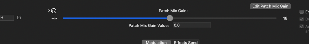
Each Patch has its own overall Gain parameter, in decibels. When sounds generated by a Patch are playing alongside sounds from other Patches, it may be helpful to punch up these sounds in the mix, or keep them low and in the background. Gain has a range of negative infinity (complete silence) to +18 db.
The most common type of Patch is the Concrete Patch. Concrete Patches are directly responsible for sample generation. Other types of Patches are Keyboard Splits, Drum Patches, and Vector Synth Patches; the other Patch types, however, ultimately, simply aggregate Concrete Patches, and rely on them for generating samples. In the documentation, the term “Patch” usually refers to Concrete Patches; the term “Concrete Patch” will only appear when context isn’t clear, and other Patch types will be referenced by their full names.
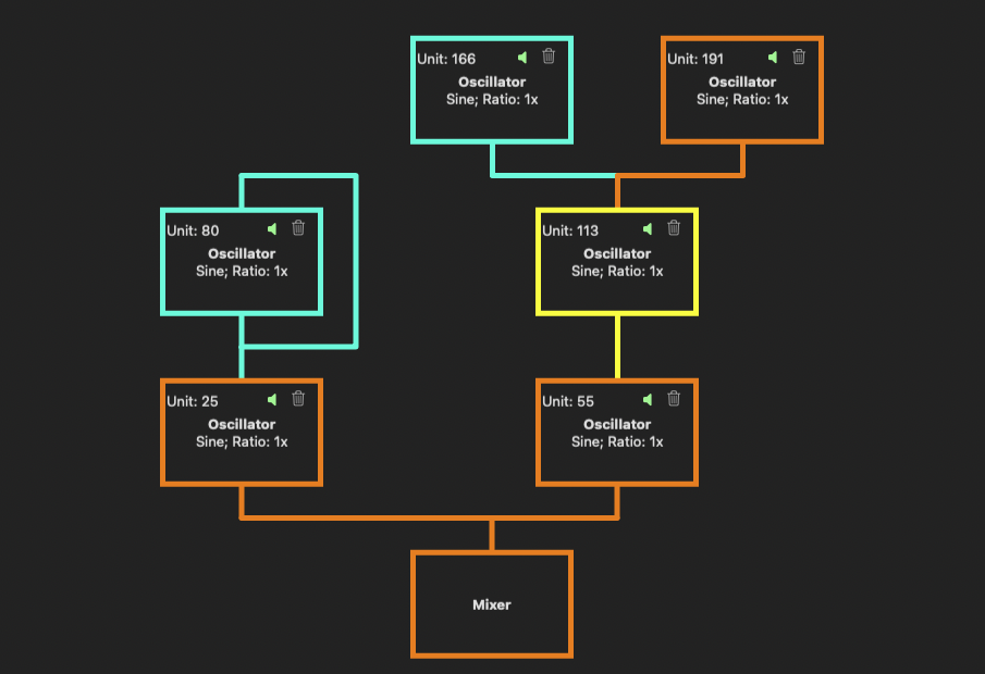
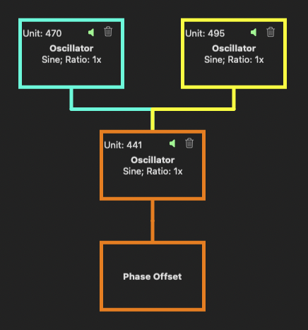
The biggest section of the window is devoted to editing the components of the Patch. The overall Patch components are divided into two tabs, Modulation and Effects Send. In both cases, the window shows a tree of components, with the Mixer at the root. The Modulation tab shows the entire Modulation Tree for the patch, with all oscillators wired directly to the mixer in the row directly above the mixer, and any modulators in rows above them. The diagram is inspired by the FM synthesis algorithm diagrams of the venerated, if not venerable, Yamaha DX7 and its successors, though the diagrams encompass a lot more in the Isle I-1. Think of sound generation starting at the top of the Modulation tree, extending down through all of the carrier Oscillators, with the finished timbre (pre-effects) directed to the Mixer, at the tree root. A similar Effects Tree diagram is displayed on the Effects Send tab, but in this case, think of the sounds starting at the Mixer, then working their way up the tree, with the final, post-effects sound being the sum of the leaves of the Effects Tree.

EDITING MIXER SETTINGS
When viewing the Modulation Tree, the Mixer is represented by a single box, with the lone word “Mixer” in the center; if you click on this box, the Mixer Settings panel appears. From this panel, you can:
- Add or remove oscillators wired directly to the Mixer, and adjust their pan position and levels in the overall sound’s mix. These Oscillators are the roots of their own modulation trees, and removing them will remove all downstream, non-shared, non-system modulators.
- Define the Amplitude Envelope shaping the entire sound produced by this Patch
- Define the initial frequency of the sound – the initial frequency is, itself, modulatable, and that modulation is separate from the timbre-defining modulation feeding into the mixer. Think of this as a really elaborate and automated pitch bend or modulation wheel (in fact, this parameter is a good choice for mapping to a MIDI controller’s mod wheel).
- The Master Panners for each channel – for stereo sound, you’ll see a Left Master Panner, and a Right Master panner; they further control the placement in the audio field of the left and right audio channels. Why assign some components to the left channel, then assign the left channel to the right and right to left? You may want to pan the overall mix, rather than keeping it fixed. This is where you would accomplish that.
- Restrict all Mixer input to single-channel (mono), and separately, only generate single-channel (mono) output. Single-channel input removes the pan settings from each oscillator wired into the Mixer, and leaves you with a single Master Panner; it can improve performance. Single-channel output forces single-channel input, and generates samples on only a single audio channel.
SETTING THE INITIAL FREQUENCY OF THE SOUND
Start with a new Patch, with only a single Oscillator, and open the Mixer panel. If you haven’t changed the tuning system, play Middle C (or any other key in any other tuning system, just trying to keep things simple) – play Middle C, you hear Middle C. Now play and hold Middle C, then drag the Mixer’s Initial Frequency slider – the pitch changes. Add a second Oscillator to the Mixer, and set its Initial Frequency parameter to a ratio of 1.5. Play Middle C again, and drag the slider around – both pitches change, but stay the same distance apart, relative to each other. By dragging the slider, you are changing the ROOT FREQUENCY of the sound. Why “root frequency” and not just “frequency”? Reset the Mixer’s slider to 1.0, then go to the original Oscillator, and change its Initial Frequency parameter to a frequency ratio of 2.0. Now play Middle C – it is not present! The Oscillators (and other components which use frequency as a parameter) are typically set to be relative to the intended note. If you wanted to transpose every sound generated by this patch, or you manipulated the Pitch Bend wheel on a MIDI controller, the sample-generating components still need to operate in the correct ratios to keep the timbre consistent.
The Mixer’s Initial Frequency parameter is fully modulatable – you can build an entirely separate modulation tree for it, apply a frequency ramp (frequency ramps will be covered in the section on Envelopes), and assign MIDI commands to it (Pitch Bend is automatically assigned to this parameter and “just works” out of the box). This is actually an excellent candidate for assigning the mod wheel, as well.
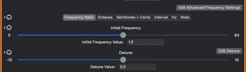
Setting frequency values anywhere in the synth works in a similar manner. You can express frequency in several different units:
- Frequency Ratio – floating-point multiple of the sound’s root frequency. The ratio is always implied to be “to 1”, meaning that if you set this value to something like 4.6667, the ratio is 4.6667:1. A ratio of 2.0 is one octave up; 0.5 is one octave down. The range of this unit is 0.0 – 64.0.
- Octaves – similar to Frequency Ratio, but the unit is a number of octaves up or down, and the value represents a power of 2, by which the root frequency is multiplied – to specify the root frequency in terms of octaves, set this to 0. 20 * root frequency = root frequency. 1.0 is one octave up, -1.0 is one octave down. The range of this unit is -6.0 to +6.0 octaves.
- Named Interval – central to most popular systems of music developed over the course of human history are a tuning system and a set of notes from which to choose. The distance between notes is often expressed in terms which are defined by the musical system, which also dictates the tuning, so when you select a particular tuning in the Isle I-1, you are bringing that system’s names for notes, intervals, rhythmic durations, etc. with the tuning. In Western European tuning systems such as 12-tone even temperament or Pythagorean, you’ll see names such as “minor 3rd” or “perfect 5th.” You can also apply this distance up or down, and fine-tune in cents.
- Semitones + Cents – a bit more technical for the geekily-minded, and also because “named intervals” and concern about the “distance between notes” is primarily limited to European functional harmony, semitones are sequential scale degrees in the tuning system. A semitone is basically one half-step in 12-tone even temperament, but in tuning systems such as Pythagorean, the ratio of frequencies is not constant from note to note. Setting relative frequency in semitones results in looking up the entry in the tuning system that many spots up or down (Named Intervals also take this approach, while providing a friendlier name). Again, this value can also be fine-tuned in cents; however, by definition, there are 1200 cents per octave (12-tone even temperament has seeped into everything, everywhere), and thus there is no attempt to adjust a cent to some value between consecutive notes in other tunings. Semitones are integer values ranging from -72 to 72; cents are floating-point, and range from -100.0 to 100.0.
- Note — A fixed value from the tuning system, with a name assigned by the tuning system itself. Whichever note you play, this is the corresponding frequency which will always be used.
- Hertz – Forego the tuning system and the note played, and just use a fixed value, in Hz.
In addition to the main frequency, all frequency values also include a Detune parameter, for making fine adjustments of up to plus or minus 10 cents. An extremenly common synthesis technique is to tune oscillators only a few cents apart. This could be done with the main frequency parameter, but separating it out allows easier control of such a minute adjustment, and without having to mentally convert something like ratio into cents (cents as a frequency ratio is a VERY small number).
ADDING AND REMOVING OSCILLATORS TO/FROM THE MIXER
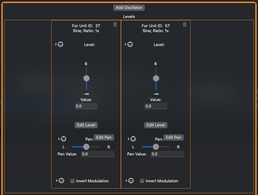
To add an Oscillator which is wired directly to the Mixer, click the Add Oscillator button at the top of the Mixer’s settings pane. Mix Levels for all of the Mixer’s Oscillators are displayed immediately below this button. To remove an Oscillator, click on the trash can icon in the Mix Levels for the Oscillator, or the trash can icon in the main window’s algorithm view. The mix level for an Oscillator is in decibels, and can be set with the Level slider to punch it up or down in the mix (center is 0.0).
The Mix Levels box, at the Mixer level, also contains a Panner to set the Oscillator’s position in the audio field. Pan is a fully-modulatable parameter, and like all modulatable parameters, it is possible to build a Modulation Tree or a Value Ramp (why not both!), or assign a MIDI command, to control it.
EDITING/MANIPULATING AN OSCILLATOR
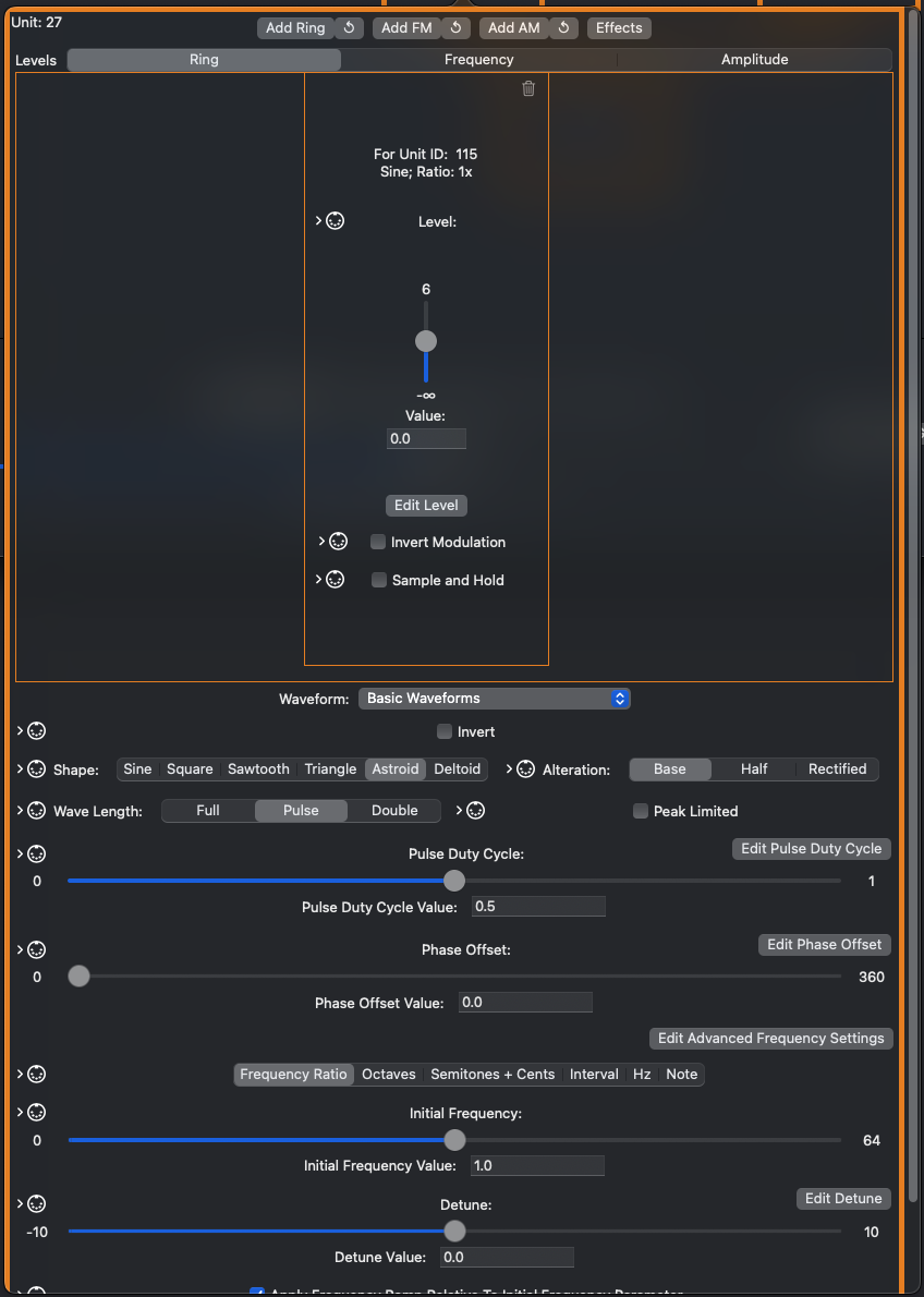
From the main window’s algorithm view on the Modulation tab, you can change and manipulate an Oscillator’s settings by clicking on its box. Oscillators, and many other components, are internally assigned a Unit ID, which is displayed to assist in identifying/keeping track of the various components of your Patch. Every Oscillator has its own Initial Frequency – this value is relative to the root frequency of the sound (unless you use a fixed frequency in units of Hz), and otherwise can be manipulated/assigned in identical fashion.
NOTE — In the Isle I-1, there is no real distinction between low-frequency oscillators (LFOs) and any other oscillator – there are just oscillators. The frequency of an oscillator can range from 0.0 (totally still) to the Nyquist Limit, or ½ the selected sample rate.
Oscillators generate samples, and thus need a sound source. The Waveform parameter allows you to select from the following sound sources:
- Basic Waveforms — 6 basic wave shapes are available:
- Sine
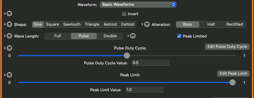
- Square, with a modulatable Duty Cycle Parameter
- Sawtooth
- Triangle
- Astroid — a waveform made available by the TX81Z by manipulating its reading of a sine wave table, here the wave is calculated via the formula for the Y-value of the parameterized curve. An astroid is a 4-point star inscribed in a circle by rolling a smaller circle, with 1/4 the radius, along the inside of the larger circle’s edge.
- Deltoid — similar in construction to the astroid wave, the deltoid is a 3-point star inscribed by rolling a smaller circle, with 1/3 the radius, along the inside of the larger circle’s edge. The deltoid wave is calculated via the formula for the Y-value of this parameterized curve.
- All of the basic wave shapes, except Square, can be altered in the following ways:
- Half — only the first half of the wave form is used, stretched to fill the entire wavelength as dictated by frequency. For a sine wave, the portion of the wave starting at 0, ascending to its peak, then returning to 0, is used, while the portion of the wave descending below 0 is not used. Several early digital synthesizers made some form of this alteration available, including the TX81Z and the CS-101. A “half wave” only occupies the top half of the full sample range; in the Isle I-1, the altered wave shape is scaled such that the wave is rendered at full amplitude.
- Rectified — in electronics, a rectifier converts an alternating current to a direct current. A rectified waveform flips the inverse portion of the wave, descending below 0, to positive values. Such a “rectified wave” only occupies the top half of the full sample range; in the Isle I-1, the rectified wave is scaled such that the wave is rendered at full amplitude. One inspiration for this alteration is the rectified sine wave available as the “Octaviant” wave on the Ondes Martenot, an early electronic instrument invented in France in the 1920’s.
- All of the basic wave shapes and their alterations can be converted to pulse waves, meaning a full wave followed by silence, within the overall wavelength dictated by frequency, or “doubled”, such that a full wave is followed by another full wave within the overall wavelength determined by frequency. These alterations have their own modulatable Duty Cycle parameter, so that for the pulse, the ratio of wave to silence can be varied, and for the “double”, the ratio of the first and second waves can vary — you can have a short first wave followed by a longer second wave. Many early digital synths offered such pulse and “doubled” waves.
- All of the basic wave shapes, their alterations, and their pulse/doubled versions, can be peak-limited — the top of the wave is squared off at some point in the wave form, as is the bottom at the inverse limit point. The peak limit can be set and adjusted in real time anywhere within the range 1 (the wave’s natural peak), to 0 (immediately capped). A peak-limited wave would lose amplitude, as it does not occupy the full sample range, so the Isle I-1 applies scaling such that the wave shape is retained, but the wave is rendered at full amplitude. As the peak limit approaches 0, the wave approaches the shape of a square wave, and becomes a square wave at 0 — this waveshaping can be applied in real time via modulation or by direct manipulation of the parameter. Again, the Ondes Martenot was one inspiration for this feature, as it has a peak-limited triangle wave available as a setting named “Creux”.
- Noise Generator – there are multiple nosie-generating algorithms available:
- White Noise
- Pink (Filtered White Noise) – white noise with a low-pass filter applied
- Pink (Fractal – Midpoint Displacement Algorithm) – A fractal approach to generating Pink Noise
- Pink (Stochastic Voss-McCartney(-Trammell) Algorithm) – a number of tiers of random numbers contribute to a sample, but each tier changes at a different rate. The result is a Pink noise with a little more bottom than the others.
- Red (Brownian) – The next sample is a random offset from the current sample, in larger steps than the Midpoint Displacement Algorithm described above. Very definite presence of low-end.
- Audio File – Samples and wavetables loaded from an audio file — .wav, .au, and .aif files are supported (.mp3, .m4a, and other format support coming soon). Audio files can also be looped and/or played backwards. The reference note for an audio file is the MIDI note at which the sound is played at its normal speed, and defaults to 60.
All of the sound sources can have their waveforms inverted by checking the Invert checkbox; thus, by setting Invert, a sawtooth wave changes direction.
The Phase Offset parameter controls where, in the waveform, a sound will start. The range is 0-360 degrees. A slider and textbox to set the value appear in the Oscillator settings pane, but as the parameter is fully modulatable, more settings are available in the Phase Offset panel – click the Edit Phase Offset button, and you’ll see a Modulation view similar to that displayed for the overall patch. The only element which appears at first is a box representing the Phase Offset parameter; click on it, and an interface opens to add oscillators to start a modulation tree, build a value ramp (an envelope controlling a parameter value), and subscribe to MIDI commands. The Limit Modulation to Min/Max Bounds checkbox does exactly what it says – if checked, modulation of this parameter will not exceed the parameter’s minimum or maximum value, if not, modulation will result in values outside the bounds (for Phase Offset, values greater than 360 are equivalent to that value minus 360, and values less than 0 are equivalent to that value plus 360). Max Modulation Width ranges from 0 to 720, and controls the maximum distance between the modulation’s low and high values.
Additional Notes Regarding Audio Files
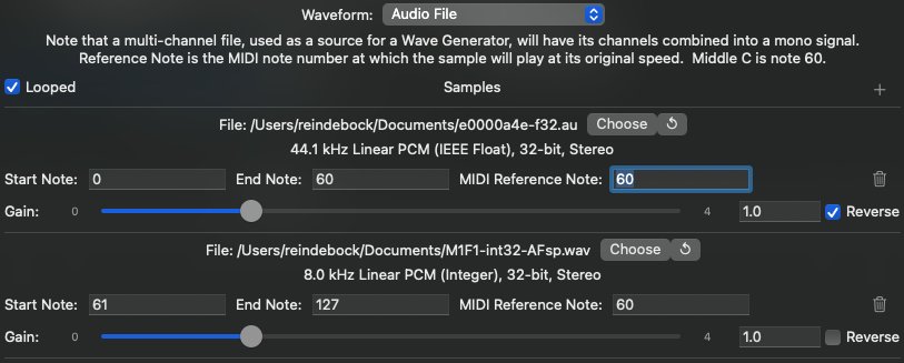
Audio Files are used as a single audio channel; if supplying a stereo audio file, for example, each channel is summed and the sum is used as a monophonic signal.
More than one sample may be used as the audio source. By default, a single file is mapped to the range of notes 0-127; however, by clicking the + button next to the word “Samples” in the section header, you can add samples. Click the Choose button to select an audio file from the file system. Click the Recycle button to select a file already included within the patch. Adjust the range values to assign the sample to a range of keys. Only the last sample assigned to a note will be triggered by that note, even though (for editing convenience) the ranges may overlap. Don’t worry, there are multiple other options for mapping multiple samples to the same key (use a second oscillator, or build a Keyboard Split patch, which DOES allow the ranges to overlap). The samples may be looped (check the Looped checkbox in the section header, to the left of the word “Samples”), and may be individually reversed via the Reverse checkbox for the file. Because each audio file has its own peculiarities, each added sample has its own Gain parameter, to mix the samples homogeneously. You are not stuck with one sample being whisper-quiet, while the sample on the next key hits you over the head like an ad for a car dealer — unless that’s what you want.
MANIPULATING AND MODULATING PARAMETER VALUES
Just about every parameter in the Isle I-1 is fully-controllable and modulatable. For parameters which represent a continuous range of floating-point values, you’ve got a pretty good arsenal of tools at your disposal.
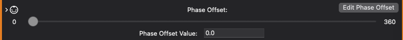
The basic view for a parameter, as seen from the larger object which contains it, gives you a slider and an edit box for typing specific values. Dragging the slider while a sound is playing will update the parameter in real-time, producing audible changes. This is useful for patch editing, though you are welcome to use it in performance (see the section on Performance-Only Mode, which allows you to manipulate live sounds without making destructive edits to the Patch configuration). The slider shows the valid range of values for the parameter — for Phase Offset, displayed above, the range is 0.0-360.0. The 5-Pin DIN icon in the upper left of this view allows you to map MIDI commands to this parameter — live sounds will reflect this parameter changing as the mapped MIDI commands are sent. The icon is a glowing green if any MIDI commands are mapped, white otherwise.
By clicking the Edit Parameter button (Edit Phase Offset in the example above), you open a dialog enabling the full set of tools — the dialog first shows you any modulation tree applied to the parameter, as shown above. Parameter values can be modulated in the same way that Oscillator frequencies and amplitudes can be modulated. If you click on the Parameter’s root box (labelled “Phase Offset” above), you’ll see a popover containing the edit controls…
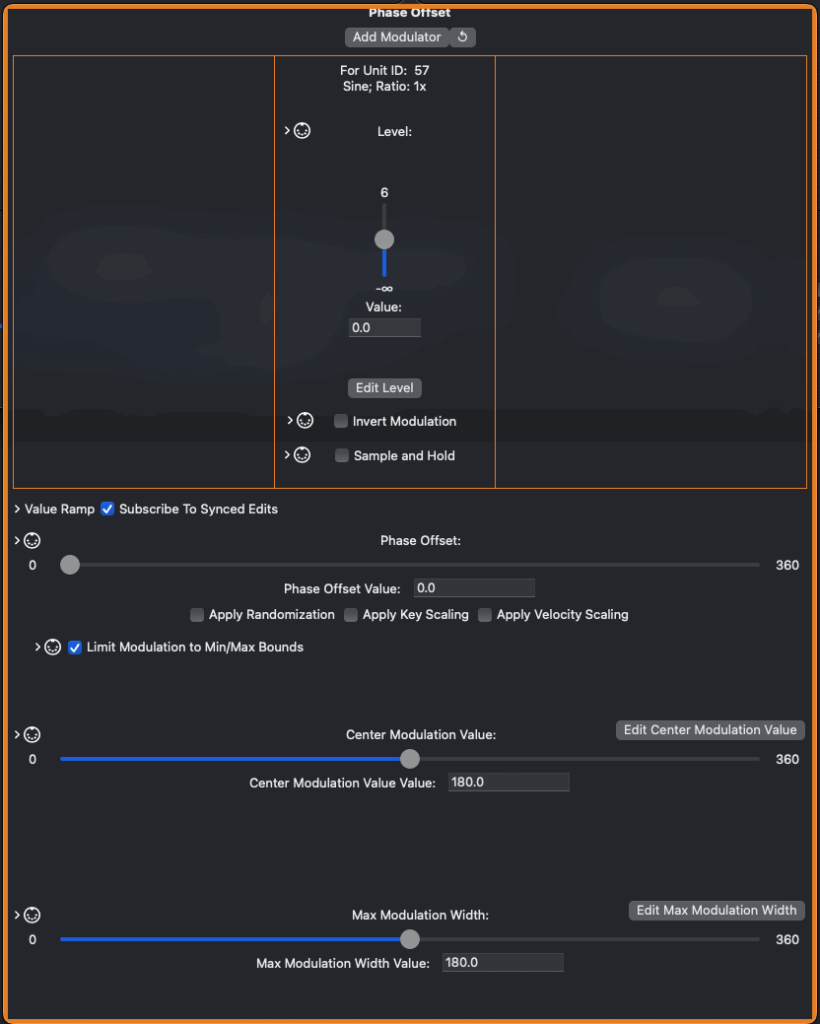
In the center of this popover are the basic controls, as displayed on the view for the containing object — the slider and edit box for directly manipulating the value, plus the MIDI command view. At the top of the view, you will see a view for manipulating the modulation relationships with each Oscillator assigned to this parameter. Multiple Oscillators can be directly assigned to the parameter; add via the Add Modulator button, or use an existing System-Level, Patch, or Parameter-level oscillator via the Reuse button. Remove a Modulator by clicking its trash can icon in the relationship parameters on the popover, or in the algorithm view.
Below the Modulators view, you’ll see a collapsable Value Ramp view — see the chapter on Envelopes for a more detailed description of Value Ramps, but the basic idea is that any parameter value can be assigned a staged ramp to modify the value over the life of a sound, including a Sustain stage — basically an Envelope, applied to any value, not just a sound or Oscilltor’s amplitude.
The Center Modulation Value parameter allows you to define the “center” of the modulation applied by a modulation tree. This will be the parameter value when the modulation signal is 0.
Max Modulation Width controls the amount of parameter change when modulation is applied — when the modulation signal is 1, the parameter value is the defined center value + max modulation width; when the signal is -1, the parameter value is the defined center – max modulation width. Modulation signal values between -1 and 1 will produce values between.
Limit Modulation to Min/Max Bounds controls whether modulation will allow a parameter to exceed the configured minimum/maximum value for the parameter. You are allowed to set this without restriction, but be sure that the parameter can work with values outside of this range if you turn it off — this could result in weird/undefined behavior, or worse due to conditions such as division by 0.
Note that Center Modulation Value and Max Modulation Width are, themselves, modulatable parameters! All of the tools available to any parameter are available to these parameters, as well, including value ramps, modulation trees, and…
Key Tracking, Velocity Tracking, and Parameter Randomization
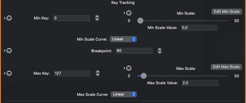
Key Tracking and Velocity Tracking (also known as Key Scaling and Velocity Scaling) can be applied to scale a parameter’s value based on distance from a breakpoint key or a “center” velocity value, setting threshold values, above which or below which a parameter will not take effect, along the way.
Think of an acoustic piano — at the bottom end of the keyboard, the strings are heavy, wound, and the longest attached to the harp. They vibrate more slowly (of course), more loudly, and take longer to decay to silence. At the top end, the strings are thin, unwound, and short. They make the highest pitches, but it takes a lot more force to make them sound at all as loud as moderate force on the bottom strings, and they fade away quickly. Key Scaling and Velocity Scaling can be used to model such phenomenon; on the other hand, they can also be used to totally uncanny effect as well.
Key Scaling, shown above, allows you to set a breakpoint key, shown as 60 (MIDI middle C). You can set this to any value between 0 and 127; the parameter will scale proportionately based on distance from this center. Min Key and Max Key define where the minimum and maximum scaling ratio will be applied. Min Key and Max Key also act as threshold values — below Min Key and above Max Key, the parameter will not provide effect at all (the actual “no effect” value depends on the parameter; for some, it really is 0, while for others it may be something like negative infinity). Min Scale and Max Scale allow you to independently set the scale factor in each direction — You can scale down to as low as 0.0 and as high as 50.0x, though the defaults are 0.0 for Min Scale and 2.0 for Max Scale. Min Scale does not have to be less than Max Scale. Note that Min and Max Scale are, themselves, modulatable parameters! You really can modulate just about anything in the Isle I-1. Scaling in either direction is applied over its own curve — Min Scale Curve and Max Scale Curve — options are Linear, Exponential, Logarithmic, Squared, and Cubed (Squared and Cubed are just convenience settings for Exponential with powers of 2 and 3).
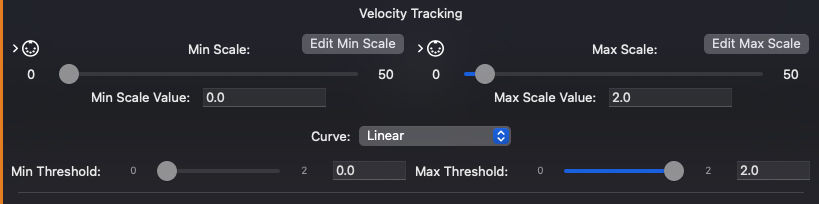
Velocity Tracking is similar to Key Tracking, but using note velocity instead. As with Key Scaling, Min and Max Scale define the scale factor in each direction, and range from 0.0 to 50.0x, and Min Scale can be greater than Max Scale. Again, both are fully-modulatable parameters in their own right. Unlike Key Tracking, however, only one curve applies across the range of velocities, and the velocity range is not configurable — it applies to the entire range of velocities. Threshold velocities define a minimum and maximum velocity, below (or above) which the parameter is not applied. You may be expecting to see MIDI 1.0 velocity values ranged 0-127 here, but while the Isle I-1 maps MIDI 1.0 values, internally velocity is represented as a 64-bit floating-point range of 0.0-2.0 (a major design goal of the I-1 is to avoid MIDI-creep into the engine — MIDI 1.0 has a lot of good points, but also a lot of limitations and is too keyboard-centric, but that’s a rant for another time and place).
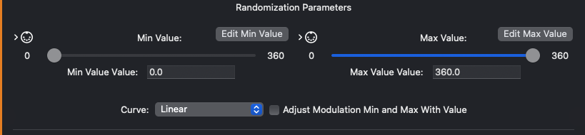
Randomization Parameters, or how to make a sound sound just a little different each time it is played — or a LOT different, depending on how you set this up. When enabling Randomization, a parameter will generate its value at the beginning of a sound, based on its Randomization settings. Any parameter can be individually randomized — frequencies, gain parameters, phase offsets, envelope stage duration, just about anything represented as a continuous floating-point value. Min Value and Max Value define a range; Curve assigns a probability distribution, and can be Linear, Normal, or Exponential. When Adjust Modulation Min and Max With Value is selected, the random value becomes the center of modulation, and the parameter’s Max Modulation Width is relative to the randomly-generated value for the individual sound. Min Value and Max Value are, of course, also fully-modulatable parameters — assign an LFO to them, then play several sounds quickly — you’ll hear the range of random values shrink and grow according to the rate of the LFO! Adjust the range via MIDI commands, sent by a foot controller or the Mod Wheel! Anything is possible!
PULSE WIDTH MODULATION
Pulse Width Modulation is a technique which changes the timbre of a square wave over time by manipulating the wave’s duty cycle. There are two ways to accomplish this in the Isle I-1.
- Create two Oscillators wired to the Mixer, set both to sawtooth, set one to Invert. On the Inverted Oscillator, set Phase Offset to 180. At this point, playing a sound will result in a square wave with a duty cycle of 50%. If you play a sound and drag the slider from 180 to other values, you’ll hear the duty cycle change; use modulation instead of dragging the slider, and you’ll hear that familiar sweep. Build a modulation tree to modulate the duty cycle in ways beyond simple back-and-forth!
- The more direct way to accomplish this is to use a single oscillator, set to square wave, and manipulate its Duty Cycle parameter directly. This parameter is fully modulatable, so you can build complex modulation trees, value ramps, and subscribe it to MIDI commands.